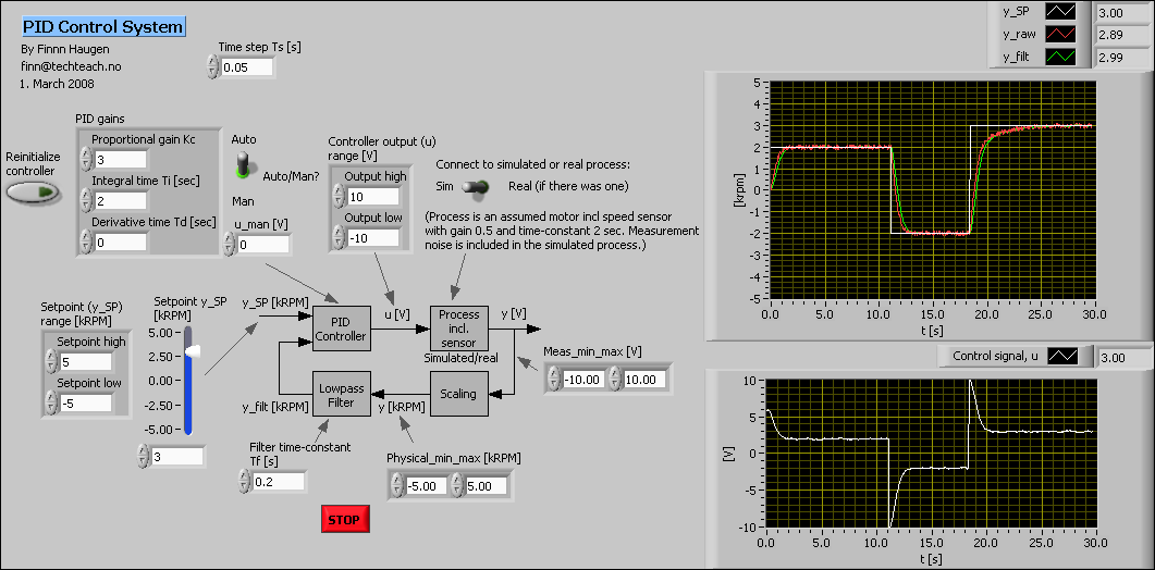

If you want a good basic example, look at the General PID Simulator.vi by searching for it in the Help > Find Examples (I searched for PID). This means your measured flow in my example doesn't change for 2 seconds, so the PID is going to try to adjust the valve continually in the same direction. Then you have your PV (essentially the flow reading) set to 50 for 2 seconds, then 30 for 2 seconds then 50 for 2 seconds (if the comment is correct). You have there a constant of 90 as your setpoint, telling the PID "I want you to be 90". A better system is to model how the valve and flow relate to one another, and then have your PV going into your PID change, as your output of the PID changes. It is like the PID is closing the valve more and more, but the flow keeps coming, so the PID closes it more and more, but the flow keeps coming. But in your simulation you are adjusting the value, but your flow being measured (PV) stays the same. But the problem is when you adjust that valve in the real world, your measured flow will actually change, and that new measured flow will go back into your PID, and then the PID will adjust the output control a little more, which opens and closes the valve more, which adjusts the amount of water flowing more, which is your simple feedback.

So you create a PID and you want to test it without the hardware, which is what you have above. So lets say you have a valve you want to control with a PID, and it will open and close and let in more or less water through a pipe. Let me try to explain the best I can with my non-academic view of a PID. The problem with testing a PID is partially that you don't have the full setup, you are creating a control for your output, but you aren't adjusting the process variable with a simulated model of your environment.


 0 kommentar(er)
